What is PowerDNA Explorer
PowerDNA Explorer is UEI’s GUI-based Application for communicating with a RACK or Cube system. Youcan use it to view the Modules on your network, explore the individual Interface Boards available ineach Module, and exercise the functionality of your UEI technology.
PowerDNA Explorer supports every UEI I/O Interface Layer, including the ability to acquire data,generate output, and otherwise employ Layer-specific features, without requiring the use of our API.The goal of this series is to cover the usage of PowerDNA Explorer over our entire product range.
AI-202: Measuring Current
To begin, we’ll look at the AI-202 Interface Board. This is a 12-channel, differential Analog Input Layerdesigned to measure current over multiple input ranges. Below, you can see the steps to readingamperage from an AI-202 using PowerDNA Explorer.
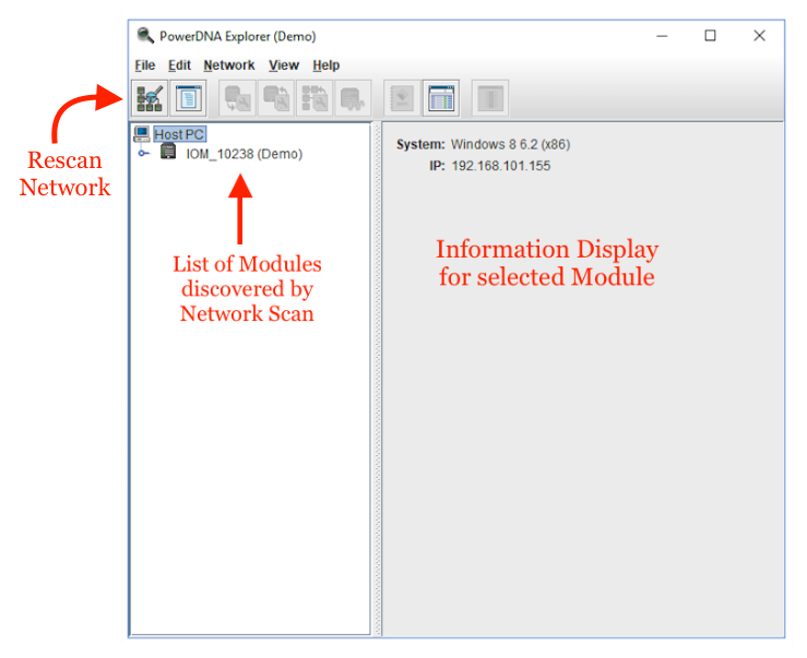
Figure 1-1 PowerDNA Explorer Initial Bootup
PowerDNA Explorer will scan the network immediately after being opened.
On the left side of the divider, you can see a list of all UEI I/O Modules that were discovered, as well asthe Host machine the application is running on. Here, the only Module found was IOM_10238, a demoUEI Cube.
On the right side you will see information about the currently selected module: the Host PC in this case.This display will change to reflect your selection.
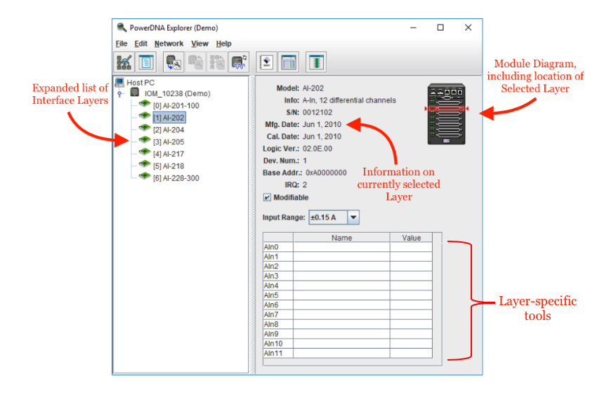
Figure 1-2 Layer Display and Tools
Expanding a discovered Module will display a list of the I/O Interface Layers contained within. Like theModules themselves, these are selectable.
When a Layer is selected on the left, the right will change to display a list of information about the layerin question, a depiction of the Module, and a set of tools for interacting with the Layer.
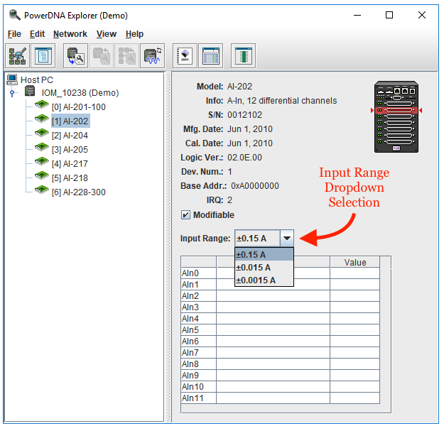
Figure 1-3 Configuring Layer
The Al-202 Interface Layer (selected above) has three available input ranges to choose from. Use thedropdown menu to select one before measuring current.
Decreasing Input Range will increase measurement accuracy.
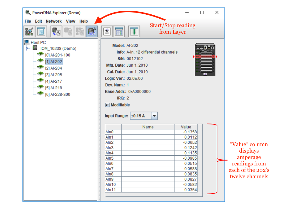
Figure 1-4 AI-202 Data Acquisition
Once you have selected the Module and Layer you want to work with, and configured the Layer’ssettings, you can begin acquiring data.
In this case, the AI-202 will read differential current values from each of its 12 channels within a 0.15Arange.
Similar Tools
There are Layers similar in function to the AI-202. The above instructions can also be used to set up dataacquisition on the following layers:
-
The AI-205 is a 4-channel Analog Input Layer that measures voltage at a maximum range of±100V.
-
The AI-217 is a 17-channel (16 differential channels, 1 single-ended CJC channel) Analog InputLayer that measures voltage at a maximum range of ±10V
-
The AI-218 is an 8-channel Analog Input Layer that measures voltage at a maximum range of±10V
The AI-228-300 is an 8-channel Analog Input Layer that measures voltage at a maximum rangeof ±300V
AI-201-100: Differential vs Single-ended Channels
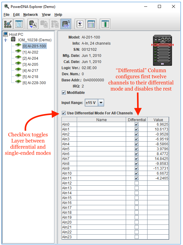
Figure 2-1 AI-201-100 Data Acquisition
The AI-201-100 is a 24-channel Analog Input Layer that measures voltage at a maximum range of ±15V.It has 24 single-ended channels, and 12 differential channels (the first 12 can be either).
There is an additional column in the table labeled “Differential”. Toggle the checkboxes here or use themaster control above to switch between single-ended and differential measurement.
AI-204: Circuit Breaker Functionality
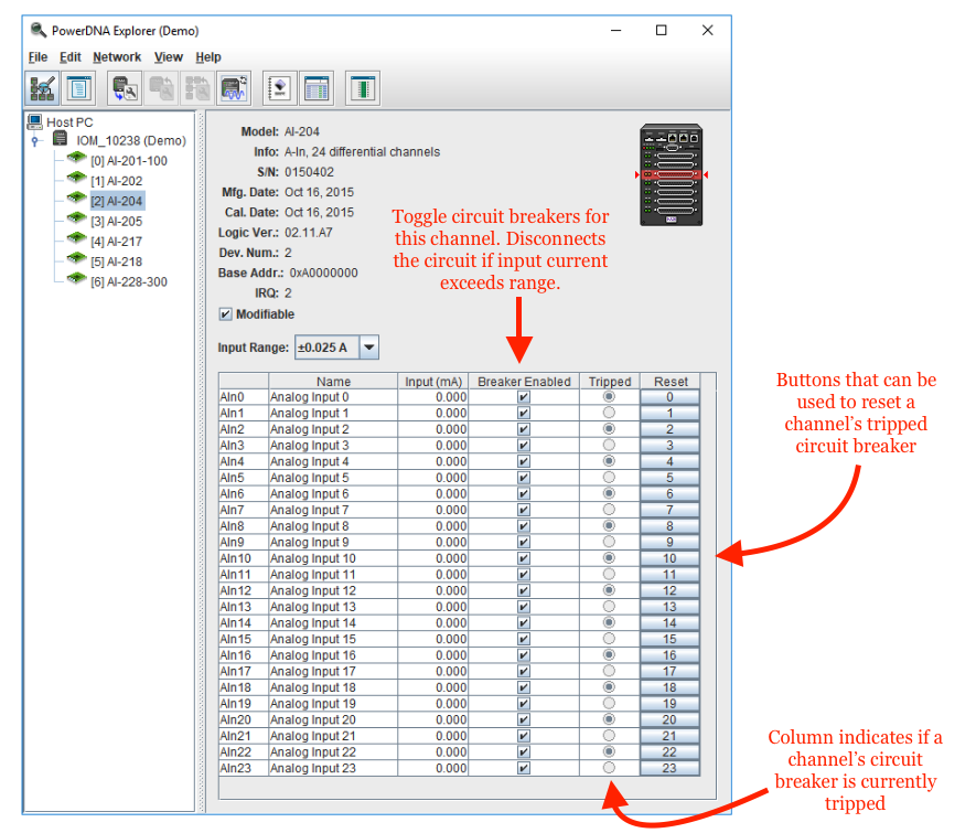
Figure 3-1 AI-204 Data Acquisition
The AI-204 is a 24-channel Analog Input Layer that measures current at a maximum range of ±0.025A. Italso has circuit-breaker that can be configured from PowerDNA Explorer. The breakers will trip if thechannel’s Input Current exceeds the Input Range for more than 100ms.
Using the Explorer Application, you can toggle circuit-breakers on a per-channel basis. Additionally, youcan determine the status of the Layer’s circuit-breakers and reset them in the case of a trip.
