Get in Touch
General
(508) 921-4600
Email Sales
Email Support
UEI Europe Office
+49 40 63698136
Email EU Sales
Visit this page for local offices and distributors.
UEI's Guardian Series Advantage

Quick Links: What is Guardian Series? | Why is it critical? | Chassis-specific Diagnostics | System Readiness | Features | Avionics | Videos & Downloads
What is Guardian Series?
United Electronic Industries (UEI) has developed a truly sophisticated and reliable on-board monitoring system we call “Guardian.” Whether you are in the field or a laboratory environment, the ability to quickly and easily test a system, monitor sensor diagnostics, as well as to detect a fault for rapid resolution is critical. Engineers demand system reliability and safeguards, without added complexity and cost. This is the advantage of Guardian series I/O boards; they offer an extensive set of built-in check, double-check parameters, such as:
- Open/broken sensor detection
- Channel self-test without disconnection of field wiring
- Current/voltage monitoring of outputs with circuit breaker functionality
- And more
You have a complete self-check capability from the chassis to the card, and the channel. With the UEI Guardian Advantage, you are assured your system is performing as expected to ensure application success.
Why is Guardian critical?
Guardian Series aims to tackle the two biggest headaches in the design process: time and money. These headaches are addressed throughout your design process. From software development to troubleshooting, Guardian offers something at every level.
It starts in software development with the use of the UEI framework (UEIDAQ), which is designed to take advantage of the Guardian features. UEIDAQ uses a single, simple, and universal API that supports all programming languages. Guardian features are part of UEIDAQ, allowing you to take advantage of their capabilities with your software. The features you’re able to program into the functionality (depending on the card) include circuit breaker functionality, open/broken sensor detection, and current/voltage monitoring.
Moreover, the savings come in the form of reduced infrastructure costs. Guardian features handle tasks that would otherwise be performed by additional hardware, e.g., voltage/current detection and circuit breaker functionality. The circuit breaker functionality offers greater protection for your investment. We understand surges happen, Guardian ensures that nothing will happen to the hardware when they do. Reduce infrastructure leads to a reduction in the overall complexity and cost of the system
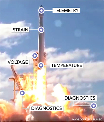
Lastly, the greatest benefit of the Guardian Series comes after deployment, when you have to troubleshoot. There are two areas where you benefit most, preventative maintenance and trace-ability. These lead to a decrease in Mean Down Time (MDT) and a lower Mean Time to Repair (MTTR). For preventative maintenance, Guardian features can be used to detect failures before they happen, such as a motor's current slowly rising over time may indicate an impending failure. This scenario would allow you to schedule maintenance on the motor when it optimizes MDT and MTTR. If you are unable to catch the failure in time, you are still protected by the programmable circuit breakers that will prevent the board from the increased current
Trace-ability is a huge factor in reducing MTTR. Many of the systems using our hardware are deployed remotely or not easily accessible. Guardian allows you to diagnose these remotely with features like field disconnect. Field disconnect allows you to remotely switch each channel to a reference voltage to perform self-diagnostics on the board. This is only one of the many features that can be used to help increase trace-ability and help make troubleshooting more efficient.
The Guardian features differ from board to board. Below is a quick view of the features of each board.
| Analog Input | ||||||
| Board | SKU | Circuit Breaker | Over Voltage | Short Detection | Field Disconnect | Open Input |
| High Speed, Simultaneous Sampling | AI-217 | ✔ | ✔ | |||
| High Speed, Fully Isolated | AI-218 | ✔ | ✔ | |||
| High Voltage, Fully Isolated | AI-228-300 | ✔ | ✔ | |||
| Thermocouple - Fully Isolated | AI-212 | ✔ | ||||
| ICP/IEPE Accelerometer | AI-211 | ✔ | ✔ | ✔ | ||
| 0-20/4-20 mA Input | AI-204 | ✔ | ||||
| Analog Output | ||||||
| Board | SKU | Circuit Breaker | Voltage Monitoring | Current Monitoring | Field Disconnect | Temp |
| Fully Isolated with Readback | AO-318 | ✔ | ✔ | ✔ | ✔ | ✔ |
| High Density with Readback | AO-333 | ✔ | ||||
| Current Output (Sourcing) | AO-318-020 | ✔ | ✔ | ✔ | ✔ | ✔ |
| Current output (sinking) | AO-319-420 | ✔ | ✔ | ✔ | ✔ | ✔ |
| Simulation | ||||||
| Board | SKU | Circuit Breaker | Voltage Monitoring | Current Monitoring | Field Disconnect | Temp |
| Simulated Thermocouple with CJC | TC-378 | ✔ | ✔ | ✔ | ✔ | ✔ |
| Simulated RTD | RTD-388 | ✔ | ✔ | |||
| Simulated RTD | RTD-388-100 | ✔ | ✔ | ✔ | ||
| Digital I/O | ||||||
| Board | SKU | Circuit Breaker | Voltage Monitoring | Current Monitoring | Onboard Reference | Monitor Switches |
| Logic Level | DIO-403 | TTL state | ||||
| 0-32 VDC Inputs | DIO-448 | ✔ | ✔ | |||
| 0-150 V AC/DC Inputs | DIO-449 | ✔ | ✔ | ✔ | ||
| Solenoid Drive (Source/Sink) | DIO-416-32 | ✔ | ||||
| Sinking outputs, 3.36 VDC | DIO-432 | ✔ | ✔ | ✔ | ||
| Low-Leakage, Sinking Outputs, 3-36VDC | DIO-432-800 | ✔ | ✔ | |||
| Sourcing Outputs, 3.36VDC | DIO-433 | ✔ | ✔ | ✔ | ||
| Low-Leakage, Sourcing Outputs, 3-36VDC | DIO-433-800 | ✔ | ✔ | |||
| Relay Outputs, Form C | DIO-462 | ✔ | ✔ | AC/DC | ||
| Solid State Relay Outputs, Form A (NO) | DIO-463 | ✔ | ✔ | DC | ||
Chassis-Specific Diagnostics
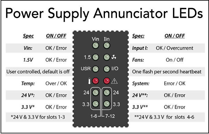
Each chassis offers a diagnostic ethernet port that allows the host to interrogate the I/O and system status of the chassis. This port can be used to monitor the following
- Internal temperature of the chassis
- Power supply voltages
- Current to the chassis
- Internal hour meter
- Dual independent ethernet ports
These features allow diagnostics to be run remotely, which saves time in the troubleshooting process.
System Readiness
System Readiness features are on all of our systems, not only the Guardian Series boards. These features include:
- Power-on self-test (POST)
- Firmware version
- Hardware configuration
- Calibration date
- Power to system
- Temperature
- Cables connected
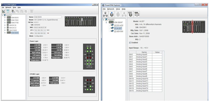
These can be viewed using PowerDNA explorer while looking at the chassis.
PowerDNA Explorer
PowerDNA explorer is a configuration, diagnostics and debugging utility that provides read/write access to UEI’s I/O boards. It can be used as a power tool to help test and troubleshoot issues with your board.
Guardian Features
Circuit Breaker

Circuit breaker functionality can help you reduce mean downtime by protecting the boards from external hardware failures. One example of this is if a digital I/O board is connected to a motor that stalls. When the motor stalls it starts to draw excessive amounts of current which could damage the board. A max current and duration can be set to enable the breakers and protect the board. In addition to a simple circuit breaker function, the API allows the breaker to be re-enabled by the software. You can either check to see if the current is below the limit or set a retry limit. This means that the circuit can protect itself and reset itself without ever being noticed. Simply put, the board can monitor itself so resources can be allocated elsewhere.
Current Monitoring

Current monitoring is essential for the circuit breaker functionality; however, it has many other benefits. One possible use is for Health and Usage Monitoring Systems (HUMS). The purpose of HUMS is predict when a component is failing and fix it when it minimizes downtime or before it fails, it causes damage to other components. For example, let’s say we have that same motor as we had in the circuit breaker section. The difference being that in this example, we monitor the current over time. While monitoring the current, we realize it is starting to rise with time, but stay within the limit we set in the software. If the rise is sustained over time, it is possible that the motor will start to fail. In this scenario, rather than wait for it to fail, you can schedule the technician to diagnose the issue when the system is going to be down.
Voltage Monitoring

Like many of the Guardian features, voltage monitoring allows for remote detection of issues with the system, such as the detection of open/short circuit and failing drive circuitry. On the digital I/O boards, voltage monitoring is important to determine whether the voltage is in a proper state, i.e. if TTL levels are set to 3V high and 1V low, is the system above, below or in the middle? If the system is in between it will not change states like it should which may indicate an issue with the system.
Overvoltage

On the analog input boards, overvoltage allows you to program a threshold that, if passed, would cause the software to throw a signal. Once the signal is detected, a technician can be dispatched to determine the cause before damage is done to the hardware.
Field Disconnect

Many of our customers have systems deployed in remote locations or in hard to access areas; it would be costly and take too much time to have a technician remove the connection from each board in order to test each channel. Field Disconnect addresses this issue with a much more efficient solution. Through our API, the channel can be disconnected from field wiring remotely while the hardware stays in place and diagnostics are run. On the simulation boards, the field disconnect can be used to simulate open thermocouples.
Onboard Reference
Onboard Reference is an extension of field disconnect. This feature can be found on our AI-228, AI-218 and DIO-449 boards. Unlike the boards with field disconnect, the channel can be switched to a reference voltage to check for faults. For example, let’s say you are receiving an incorrect voltage reading and wish to isolate the issue. A faulty card can be eliminated by using the field disconnect feature to test whether it is reading correctly. Once it has been proven that the card is not the issue, a technician can better focus on the attached equipment or wiring.
Temperature

Temperature readings, found on our analog output and simulation boards, can be used in conjunction with the current reading to determine if hardware is failing. Continuing the situation described in the current monitoring section, a rising current will result in a temperature rise due to the power dissipation. The rise in temperature can be monitored to determine the priority that needs to be placed on fixing the failing hardware.
Open/Short Detection

Certain analog input boards and the VR-608 universal speed input board, in conjunction with our API, offer the ability to detect open inputs. In addition to open input detection, the AI-211 board offer short circuit detection. This is useful in quickly diagnosing issues with the system. You can program a periodic check of the system for open/short circuits. Once detected, a technician can be dispatched to troubleshoot and fix the issue
Monitor Contacts
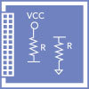
No need for external “wetting voltage” for your contacts – we can supply the pull-up resistors to Vcc or the pull-down resistors to ground. This eliminates the need for external hardware, reducing the size and cost of the system. This helps increase the traceability which helps with troubleshooting any issues that may arise.
Avionics
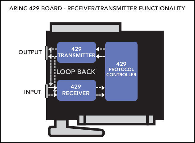
For the following ARINC-429 boards, Guardian series provides a receiver connected to each transmit channel. This allows the application to confirm the correct information was written to the bus. Monitoring the bus in this way eliminates the need for extra wiring to troubleshoot whether the correct information was received.
Videos
Why You Need the UEI Guardian Advantage
How do you know your system is working right or getting accurate data? UEI's Guardian Series brings monitoring to a whole new level.
UEI Health Monitoring and Diagnostics
United Electronic Industries hardware provides unique on-board health monitoring and diagnostics features, from the processor down to the individual I/O channels, including Built-in-Test, and our PowerDNA Guardian Series I/O boards. These features give you valuable feedback to help ensure successful deployment of our rugged systems.
Pulse Width Modulation (PWM) Overview
United Electronic Industries manufactures a number of products specifically designed to monitor and control pulse width modulation (PWM). In this video we explain the characteristics of PWM and demonstrate a few real world applications using the UEI Guardian Series boards.
UEI's Technical Master Class: Reliable On-board Monitoring & Verification For Your System
In this Master Class, application engineer Austyn Turner provides a detailed tour of UEI's sophisticated, reliable on-board monitoring diagnostics we call “Guardian."
Related Applications
UEI has a wide variety of solutions for your defense and aerospace applications. Please click on the below to learn more.
 |  |
