In almost every electrical engineer’s coursework, they will learn about the Wheatstone bridge and possibly wonder where this would ever be used in the real world. Low and behold, the strain gauge (or sometimes gage), a widely used and simple electrical device. Whether you’re measuring the torque on a turbine, force on a propeller, or merely weighing a package on a scale, a strain gauge allows for precise measurements while needing only a few external components.
Some things to be aware of when selecting and measuring a strain gauge:
- Bridge configuration – A Wheatstone Bridge is a bridge of 4 resistors, each referred to as a “leg” of the bridge. A strain gauge may be configured as a single leg, referred to as a quarter bridge. To complete the bridge the user must provide bridge completion resistors where the accuracy of these resistors can impact the output voltage of the bridge. In the half-bridge configuration, typically two legs are strain gauges, doubling the effective output of the Wheatstone Bridge. And finally, there is the Full Bridge configuration which again effectively doubles the output voltage and typically have the best performance over temperature. See the image of a quarter bridge strain gauge below.
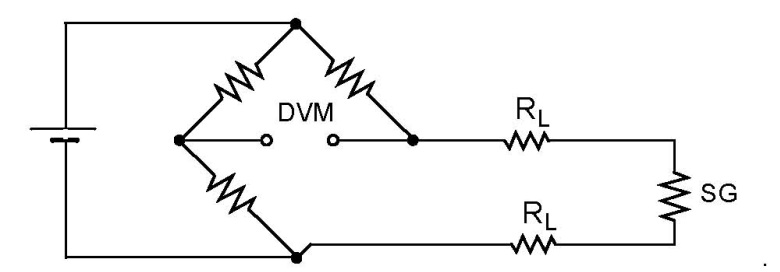
Quarter Bridge Strain Gauge UEI's DNx-AI-224 4-channel strain gauge input board and DNx-AI-208 8-channel strain gauge input board both support full, half, and quarter bridge configurations. - Precise Voltage Source – Since a strain gauge is simply resistors, the output will be determined by overall resistance and the supplied voltage. A precise, stable, voltage source gives deterministic and repeatable results throughout the measurement period. Another solution here would be to trade the precision voltage source for a stable source and measure the voltage applied to the bridge. The added benefit here is compensating for line losses, in case of long leads to the device.
- Accurate input (with high gain) – The output of a strain gauge can be in the microvolts to millivolts range. An analog input with a range of +/-10V would result in wasting many bits of the resolution. Instead, to get accurate measurements you will want an input with a high gain to increase the effective number of bits (ENOB) used. It may also be beneficial to have a filter at the input so that the same high gain is not applied to input noise.
There are certainly other factors when measuring a strain gauge: performance over temperature, nulling a start offset, cabling to reduce noise, or applying a shunt value to test strain values before they even occur (to name a few). However, the main three bulleted above will typically have the most effect on your end results. Learn more in the video below.
UEI's Strain Gauge Boards
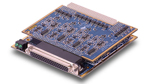 | UEI’s DNx-AI-224 4-channel high speed, strain gauge input I/O board features 18-bit resolution - 100 kilosample/second, simultaneous sampling on all channels, built-in anti-aliasing filters, full, half, and quarter bridge inputs, 120, 350, and 1000 ohm bridge completion, and built-in tension/compression shunt calibration resistors. Click here to learn more. |
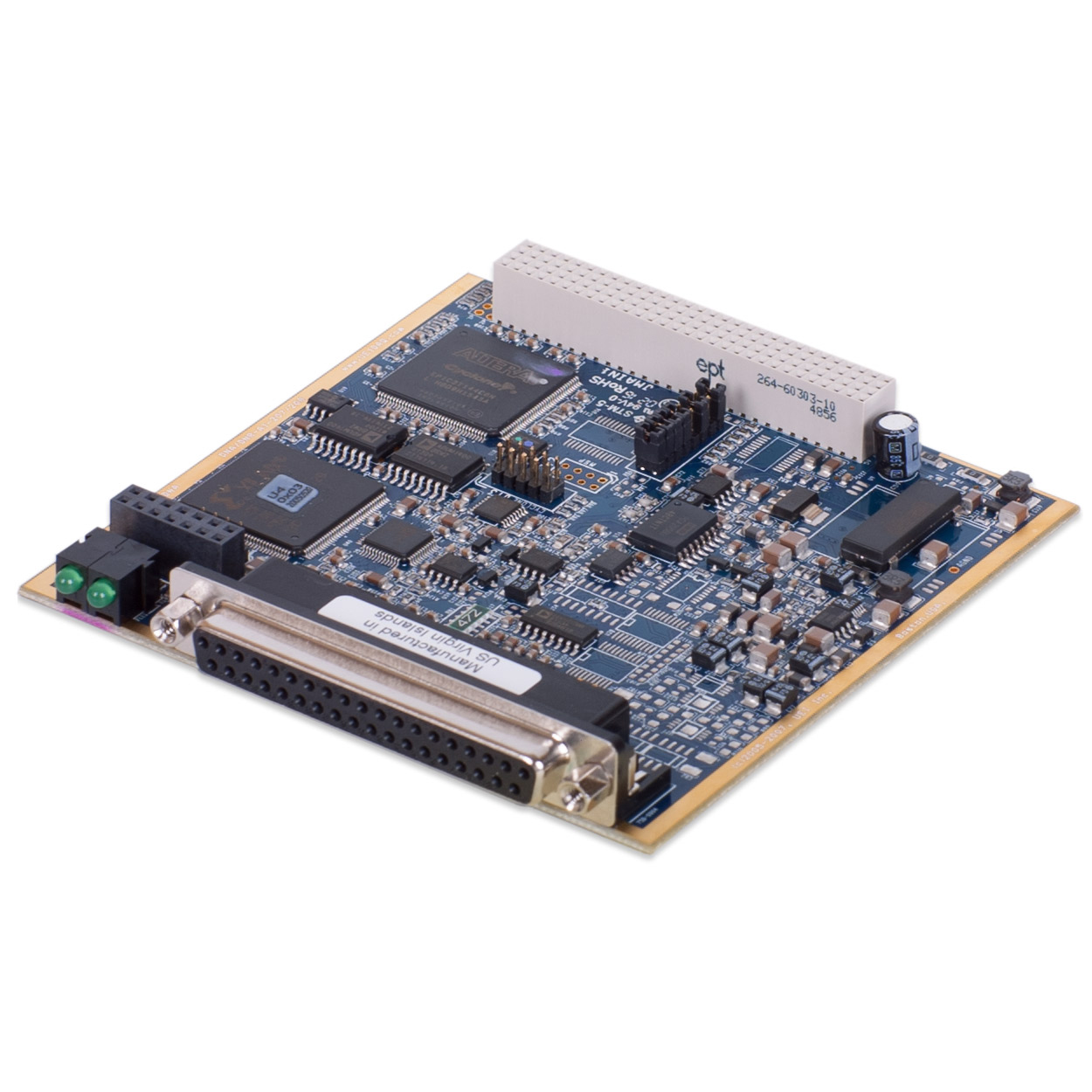 | UEI’s DNx-AI-208 8-channel, 18-bit, 1kS/s per channel, strain gauge input I/O board features 18-bit resolution, 2 wiring schemes (4- and 6- wire), overvoltage protection (-40V..+55V), full, half, and quarter bridge inputs, software for onboard shunt calibration, per channel built-in averaging engine from 5Hz, 4096 samples to 1000 Hz, 4 samples. Click here to learn more. |
Contact our support team at (508) 921-4600 or support@ueidaq.com to learn more!